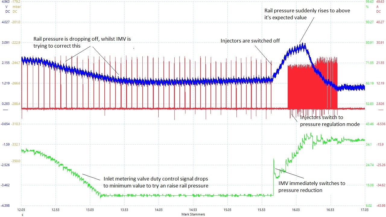
The following waveforms are taken from a 2011 Ford Mondeo 2.0LTDCi with Delphi injection.
They show the fuel pressure control system in operation during a pressure control fault.
The vehicle had been suffering from intermittent power loss, with flagging of MIL and recording a fuel pressure sensor fault.
During road test, whilst monitoring the rail pressure, it was noted that the 'desired' and 'actual' values did not always follow and in fact you could see that sometimes it was lower than desired and sometimes higher than desired.
This condition is most commonly caused by Inlet Metering Valve (IMV) sticky operation.
The first image illustrates what could be mistaken for that.
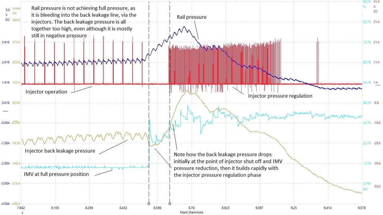
This image is similar to the first, only it shows the actual back pressure in the injector leak off circuit, whilst driving the vehicle.
The waveform below shows the switch on event for a Bosch LSU4xx type broadband oxygen sensor, fitted to DV6 type engine management system (EDC17C)
Unlike a petrol engine system, the sensor is only used to calculate injection 'drift' adaption. The following conditions must be met to enable the sensor's operation.
•Coolant temperature between 15°C and 100°C
•Air temperature between 13°C and 32°C
•Fuel temperature between 10°c and 100°c
The voltages for the 3 wires on the sensor side of the connector are as follows:
Red wire,pin 6 - 2.95 vdc from chassis ground, Black wire,pin 1 - 2.95 vdc from chassis ground, Yellow wire,pin 5 - 2.50 vdc from chassis ground
Pin 2 connects the 'trimming' resistor and does not continue to the sensor.
The grey and white wires are for the heater element.

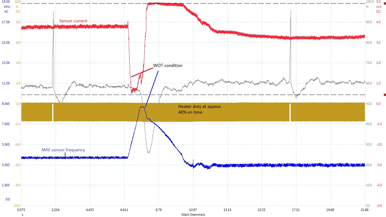
The waveform below shows the 'WOT' event for a broadband oxygen sensor, fitted to the same DV6 type engine management system (EDC17C)
You can see how the current drops to near zero under 'WOT'and back up to around 3mA which is approximately 3.5 Lambda factor.
This sample was taken from a DV6 EDC16 system. It represents a good signal.
The voltage was captured using an active differential probe.
Orientation of the voltage is irrelevent, as these injectors do not use a chassis ground.

The next image is taken from the same vehicle as above, only in this case there was a significant internal ECU fault, causing the injectors to fail.
The ECU records DTC's for all 4 injectors 'shorting between pins'. The results shown here illustrate the increase in injection duration, in an attempt to keep going.
You can see that the current has reduced and the voltage has lost the positive portion, (subjective orientation only).
This is the result of internal shorting of the injector driver stage.

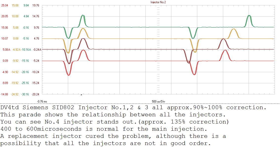
The waveform below shows a parade of Piezo injectors, one of which is faulty and so has a high correction
The wave form below is taken from a 206 DW8 diesel engine, running at idle.
It shows the crankshaft sensor, which in this case represents 'TDC' only and the Injector 'needle lift' sensor on cylinder No.1

The wave forms below are taken from a Citroen C8 HDI, (same as 807 DW10 RHT engine), accelerator pedal sensor. The reported fault code was 'P0221', accelerator pedal sensor coherence fault and was intermittent. The signal, at first glance, looks perfectly ok. On closer inspection you may note that the signal voltages are not correct, even although the relationship between the two signals is correct, the amplitude is incorrect.
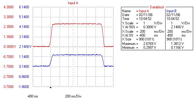
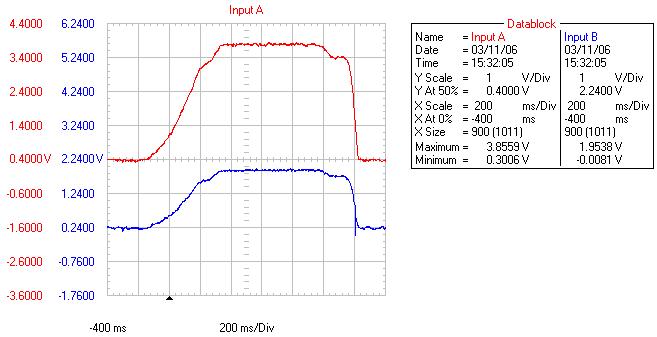
The following wave forms are taken from the same vehicle as above, only with a new accelerator pedal sensor fitted. Now you can see the comparison and relationship of the sensor signal voltages. ('A' is double 'B' and the voltage amplitude is correct).
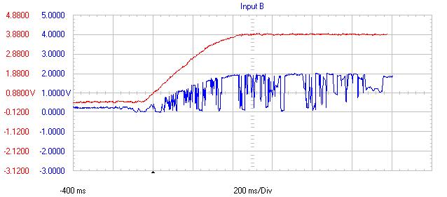
The wave forms below are taken from a 306 DW10td HDI accelerator pedal sensor. Coherence fault recorded and the operation was knotchy.
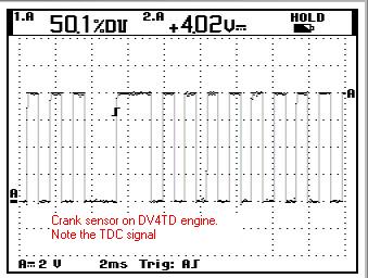
Engine speed sensor signal, Hall effect. DV4td engine.
The image below is also a 'Trendplot' recording. It is a DW10 HDI engine temperature sensor failing rapidly. This fault was not detected by the ECU.

Last Reviewed: 16 April 2021Copyright © 2004...2021 Mark Stammers